Differential Signaling Tutorial
The transmitter injects a small current eg 35 mA into one wire or the other depending on the logic level to be sent. Signal Integrity TUTORIAL Differential Signalling A differential signaling system uses two dedicated wires to transmits two different voltages which are compared at the receiver.
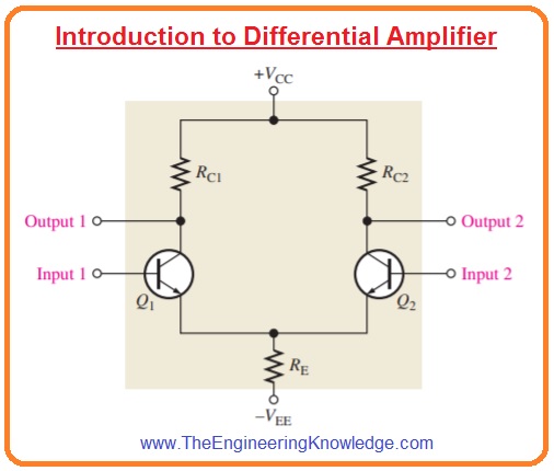
Introduction To Differential Amplifier The Engineering Knowledge
Cons of differential signaling.

Differential signaling tutorial. Using twofour channels oscilloscope is the cheapest method which handles acceptable results. Theres really only one major con of differential signaling but it is a pretty big oneyou need twice as many conductive paths to provide a differential signal as you do for a single-ended signal. Any interference that a differential signal soaks in gets distributed evenly between the positive and negative traces which reduces any change in amplitude that external EMI issues can cause.
28GbS signaling is already being successfully shipped in high performance servers routers and switches. The sig-nal has a typical driver offset of 12 V and the receiver accepts an input range of ground to 24 V. This allows rejection of common-mode noise picked up along the interconnect of up.
Differential signaling also has the added benefit of reducing any incoming electromagnetic interference or crosstalk from other noisy traces. How does differential signaling work. One carries the signal and the other carries the inverted signal.
So one information signal requires a pair of conductors. When these two signals arrive at the amplifier they will not only receive the benefits of noise cancellation but will also double in voltage subtracting a negative signal adds to the positive signal. This allows fully differential signals to be 6 dB louder double the signal level than unbalanced and non-differential balanced signals.
The differential receiver is a high-impedance device that detects differential signals as low as 20mV and then amplifies them into standard logic levels. This combination ensures a robust noise margin that tolerates the attenuation from long cables. Differential signal measurement in practice.
A differential probe is expensive but handles a better accuracy. Benefits of differential signaling. Now as the signals travel down the traces they are both affected by common-mode noise.
Two copies of the original signal are sent down a pair of paths with one inverted relative to the other. Differential pair signal paths. The Tx must have an enable pin.
Differential signaling with a very sensitive 200 mV Rx and a healthy 15 V Tx differential output voltage VOD. This video tutorial walks through how to use Differential Pair Routing with Fusion 360s PCB layout editor. Space and cost requirements can impact the feasibility of using a differential pair in your design.
در آپارات وارد شوید تا ویدیوهای و کانالهای بهتری بر اساس سلیقه شما پیشنهاد شود وارد شوید. The differential data transmission method used in LVDS is less susceptible to common-mode noise than single-ended schemes. This is a thorough treatment of all of the topics that must be considered in order to be successful as the speeds of differential pair signal paths continue to increase.
To measure a differential signal we have two options one is using a differential probe and second is using a two channels oscilloscope. Differential signaling which is less common than single-ended signaling employs two complementary voltage signals in order to transmit one information signal. The differential transmission uses two wires with opposite currentvoltage swings instead of the one wire used in single-ended methods to convey data information.

Controller Area Network Can Programming Tutorial 6 Single Ended Vs Differential Signals Youtube

Differential And Common Mode Signals Youtube

Lvds Enables High Speed Signal Distribution In 3g Base Stations
Differential Signaling Designing For Long Fast Or Noisy Applications Youtube