Asm Chart Tutorial
They are used to represent the flow of tasks to be performed by data path circuits and control circuits. Assembly language ASM is not a mythical dark art in fact its fundamental to computers operating at all.
Asm Charts Finite State Machines Electronics Tutorial
An ASM chart representation can easily be transformed to VHDL code.
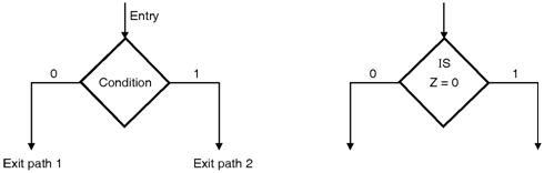
Asm chart tutorial. Section text global _start must be declared for using gcc _start. It can also be extended to describe FSMD FSM with a data path which is discussed in the next two chapters. Components of ASM Charts Decision box J 0 1 Decision box has two or more branches going out.
Basic Components of ASM charts. The ASM chart differs from an ordinary flowchart in that specific rules must be followed in constructing the chart. The ASM method is composed of the following steps.
The following diagram shows the three main components of an ASM chart. Decision is made based on the value of one or more input signals eg. ASM charts are similar to flow charts.
PIC16F84-04P which operates up to 4 MHz and is housed in a plastic DIP package1 ThisisaproductofMicrochip Inc. Understand and map out a state machine diagram in UML using Lucidchart. 3Design the datapath based on the ASM chart.
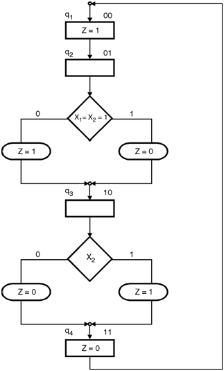
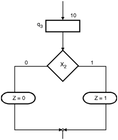
There are 2 inputs so there are 22 4 possible conditional branches for each state. Signal J Decision box must follow and be associated with a state box. Assembly Programming Tutorial PDF Version Quick Guide Resources Job Search Discussion Assembly language is a low-level programming language for a computer or other programmable device specific to a particular computer architecture in contrast to most high-level programming languages which are generally portable across multiple systems.
For concreteness Ill use just one processor the PIC16F84. Process Mapping TutorialA review of the main types of process maps how to analyze a process map and guidelines on best practices. When these rules are followed the ASM chart is equivalent to a state graph and it leads directly to a hardware realization.
In this tutorial we focus on Intel-32 processors like Pentium. To overcome this difficulty Algorithmic State Machine ASM charts can be used. Explore our vast UML shape library and use our state machine diagram templates.
Chapter 4 Algorithmic state machines and finite state machines 69 αij α1ij α2ij. PIC assembly language just enough to get you started. Logic Design and Microprocessors by Lam OMalley and Arroyo Note.
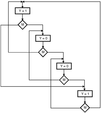
Tell linker entry point mov bx 3 for calculating factorial 3 call proc_fact add ax 30h mov fact ax mov edxlen message length mov ecxmsg message to write mov ebx1 file descriptor stdout mov eax4 system call number sys_write int 0x80 call kernel mov edx1 message length mov ecxfact message to write mov ebx. Note that for the path Y6Y7 operator Y7 follows operator Y6 immediately without. Above all else - KEEP IT.
An ASM chart is constructed of a network of ASM blocks. Its free to register so sign up today. Following are the three basic components of ASM charts.
Equivalent to a node in a state diagram or a row in a state table. Thus the decision is made in the same clock cycle as the other actions of the state. To follow this tutorial you will need.
Figure 72 modified Fundamentals of Computer Engineering. 5Design the control logic based on the detailed ASM chart. αHij where αhij h 1H is the product for the h-th pathLet us call αij a transition function from operator microinstruction Yi to operator microinstruction Yj.
2Convert the pseudocode into an ASM chart. To be very precise Ill use the 2. 4Create a detailed ASM chart based on the datapath.
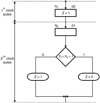
A copy of NASM assembler. 1Create an algorithm using pseudocode to describe the desired operation of the device. Elements used in ASM charts 1 Output signals or actions Moore type State name Condition expression 0 False 1 True Conditional outputs or actions Mealy type a State box b Decision box c Conditional output box State Box State box -represents a state.
A copy of Linux operating system. An IBM PC or any equivalent compatible computer. Constructing an ASM Chart from a Timing Diagram Construct an ASM chart that could yield the following timing diagram.
I take a quick look at a very simple assembly lan. An ASM block consists of one state box and an optional network of decision boxes and conditional. Assembly language is dependent upon the instruction set and the architecture of the processor.
Asm Chart 2 Bit Up Down Counter Finite State Machines Electronics Tutorial
Asm Chart For Signal Generator Finite State Machines Electronics Tutorial
Asm Chart For Signal Generator Finite State Machines Electronics Tutorial
Asm Chart For Signal Generator Finite State Machines Electronics Tutorial