Class E Power Amplifier Tutorial
In picture 24 there is a representation of an ET transmitter system. Notes on designing class-E RF power amplifiers Bill Slade 4 May 2010 Abstract Perhaps the most difficult part of any design process is the synthe-sis of suitable candidate circuits based on the results of an analytical model.

Pdf Notes On Designing Class E Rf Power Amplifiers
It can be driven using square wave or.
Class e power amplifier tutorial. Class B Amplifier is twice as efficient as class A amplifiers with a maximum theoretical efficiency of about 70 because the amplifying device only conducts and uses power for half of the input signal. Class E amplifier is a highly efficient power amplifier which uses switching topologies and works in radio frequencies. Class F is high impedance amplifier in respect of the harmonics.
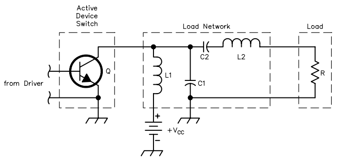
Typically Class-E amplifiers see References 1-6 can operate with power losses smaller by a factor of about 23 as compared with conven-tional Class-B or -C amplifiers using the same transistor at the same fre-quency and output power. The following figure shows the circuit diagram for Class A Power amplifier. Design specifica-tions of the amplifier are to achieve an output RF power of 5 W from an input driving level of 05 W and drain effi-.
Class AB Amplifier has an efficiency rating between that of Class A and Class B but poorer signal reproduction than Class A amplifiers. Class E Kits and Parts. Classes discussed in Chapter 2.
RF Amp for 80 meters. For ex-ample a Class-B or -C power stage operating at 65 collector or drain. The design accuracy of class-A power amplifier based on the small-signal S-parameters was investigated where compression in the power gain was used as an indicator for design accuracy.
Class-B amplifiers are more efficient than Class-A amplifiers. Class-E Power Amplifier Design 16 21 Introduction 16 22 Class E Theory of Operation 18 73 Class-E Amplifier Design 23 24 Differential Architecture 28 25 Bondwire Inductors 3 1 26 Source Impedances 32 27 Gain Stage Design 35 28 Load Pull Analysis 38 29 Impedance Matching 40 Class-E Power Amplifier University of Toronto. Typical Class-E Power Amplifier Design For the clarification of the goals of this paper a power amplifier circuit has been designed and simulated using a commercial microwave CAD program.
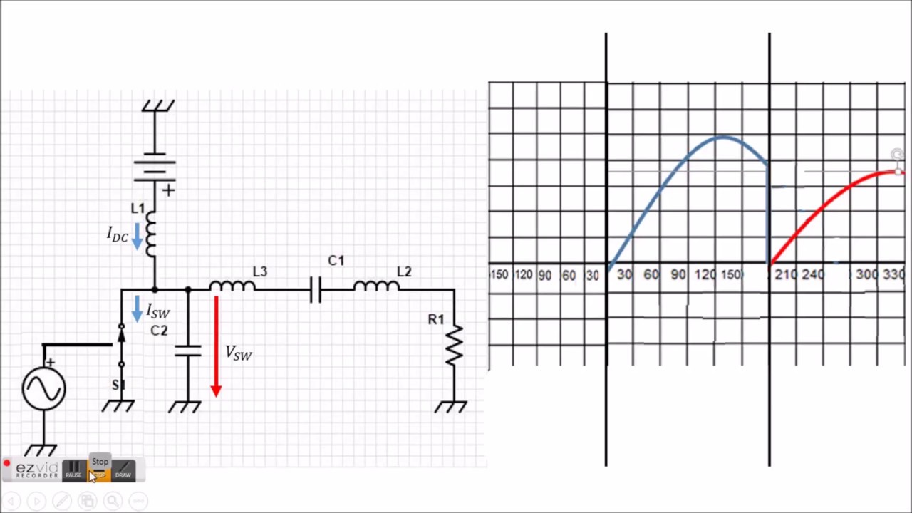
In transconductance amplifiers the current through the active device is known a priori and so the voltage waveform is simply the voltage resulting from that known current forced through the known load impedance. Using a lower power transmitter as an RF source A to D converter Pulse Width Modulator and power supply. AC THEORY MODULE 05PDF 1 E.
A power amplifiers classes A AB B C F E etc and design techniques Load-pull and large-signal S-parameters techniques are presented. 12V low power and low RF frequency 433MHz is a major challenge. Class E operates at a fixed power set by Class E output network Variable power best done by changing supply voltage May be able to reduce power from preset maximum by lowering TX gate drive bias but at reduced TX efficiency.
What Can Class-E Do for Me. 24 MOSFET RF Amplifier - Step by Step. Therefore a typical Class-B amplifier will produce quite a bit harmonic distortion that must be.
However they are much less linear. The instantaneous efficiency of a Class-B Power Amplifier varies with the output voltage and for an ideal PA reaches π4 785 at PEP. COATES 2007 -2012 Power Amplifiers Introduction to Power Amplifiers Power Amplifiers Amplifier circuits form the basis of most electronic systems many of which need to produce high power to drive some output device.
A single pole switching element and the tuned reactive network is the main component to use with the class E amplifier. The use of transformer permits the impedance matching resulting in the transference of maximum power to the load eg. Design and assembly of a class E power amplifier 2GHz 6 213 Envelope Tracking Transmitters Similar to that of an H-EER transmitter the input signal of the PA is not a constant envelope signal with phase information but a complex-signal envelope.
This work focusses on a simplified analytical model for the class-. From the above figure it can be observed that the transformer is present at the collector as a load. Analog Modulator Class H and power supply.
The class E Power Amplifier which is one type of switch mode PA is preferred in such a scenario because of its higher theoretical efficiency compared to linear power amplifiers. A controllable class E RF power amplifier design implemented in 013µm CMOS process is presented. In class-F amplifiers the waveforms are assumed to be composed entirely of low-order harmonic.
VFO for 160 80 meters. Overall Schematic of a complete modulatorpower supply.

Class E Power Amplifier Design
Vk1sv Class E For Beginners Home Page

Developing A Mode Locked Class E Power Amplifier For Rf Applications Ee Times
Class E Configuration Theory Of Operation Youtube